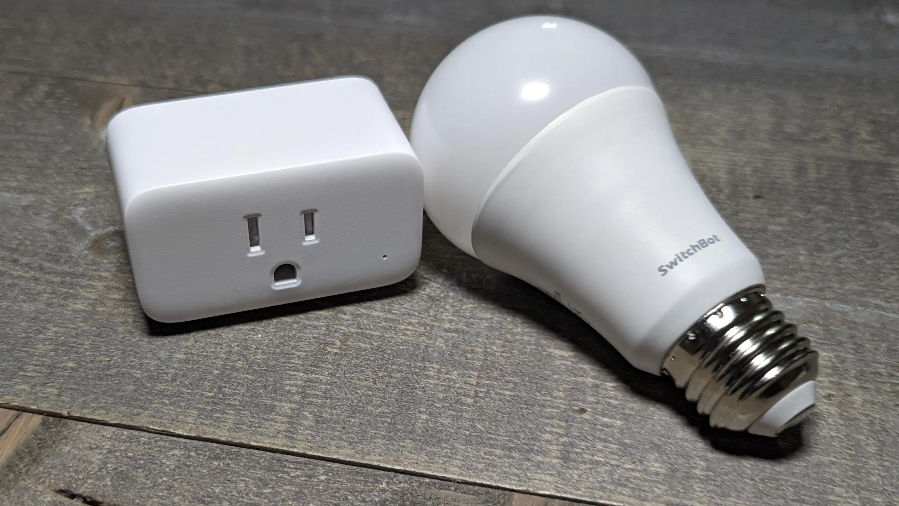
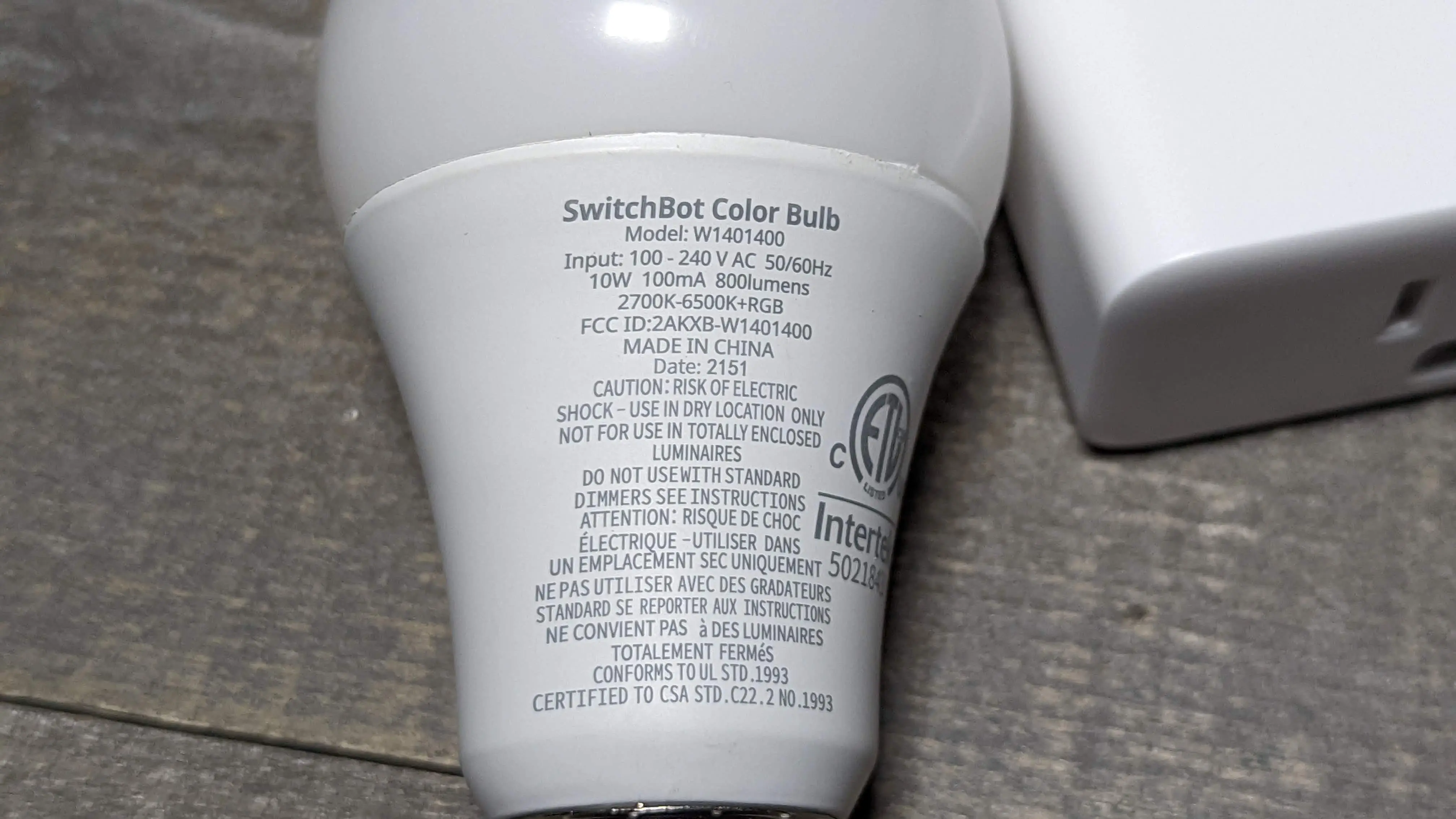
SwitchBot RGB+CT E26 Bulb W1401400
5 Channel RGB+CT E26 800 lumen bulb with an ESP32-C3. This smart bulb can currently be upgraded via the SwitchBot OTA process - GitHub or digiblurDIY Video, no soldering or manual flashing invovled.
Purchase via Amazon
Purchase via SwitchBot Store
Supported in TASMOTA 12.0.2.2 or later, use this TASMOTA Stock Bin file or Bluetooth enabled until the next standard Tasmota release. Thanks to Cossid for his efforts!
Please note the required SetOption below for correct color order. A user configurable brightness limit of default of 9 is set via the template SM2335 Dat option. This was found to be close to stock as possible. Setting this higher could create power supply issues, excessive heat/fire, LED flame out errors, etc.
As noted in the video walkthrough, if your device already has the latest firmware you will need to reference the video at 9:14 or this Github thread to send over the bluetooth update packet to send over the bluetooth update packet to initiate the trigger from your local SwitchBot OTA process.
Quick Setup via TASMOTA Console Command
backlog template {"NAME":"Switchbot E26 Bulb","GPIO":[0,0,0,0,9128,9088,0,0,0,0,0,0,0,0,0,0,0,0,0,0,0,0],"FLAG":0,"BASE":1}; module 0; so37 25; so59 1
TASMOTA Template
{"NAME":"Switchbot E26 Bulb","GPIO":[0,0,0,0,9128,9088,0,0,0,0,0,0,0,0,0,0,0,0,0,0,0,0],"FLAG":0,"BASE":1}
GPIO Layout
| GPIO | Component | Description |
|---|---|---|
| GPIO04 | SM2335 Dat | Data - Brightness limit - Default 9 |
| GPIO05 | SM2335 Clk | Clock |
TASMOTA Settings
| Setting | Description |
|---|---|
| setoption37 25 | Set the correct RGB+CT order |
| setoption59 1 | Report light state changes via MQTT |
Rules
None necessary.
Moving to ESPHome
Build the new ESPHome device using the YAML example below and tweak for your network or entity names as needed. In ESPHome choose install, manual download, then once the firmware is built choose the LEGACY download option. Open the Tasmota web GUI on the switchbot bulb, select firwmare upgrade and upload the legacy bin downloaded in the previous step. Allow the devices a few minutes before power cycling it if it does not appear on your network.
ESPHome YAML
esphome:
  name: bulb-switchbot1
  friendly_name: bulb-switchbot1
  platformio_options:
    board_build.mcu: esp32c3
    board_build.variant: esp32c3
# added the line below to prevent bootloops when flashing modern bin via serial
    board_build.flash_mode: dio

esp32:
  variant: ESP32C3
  board: esp32-c3-devkitm-1
  framework:
    type: esp-idf
    sdkconfig_options:
      CONFIG_BT_BLE_50_FEATURES_SUPPORTED: y
      CONFIG_BT_BLE_42_FEATURES_SUPPORTED: y
      CONFIG_ESP_TASK_WDT_TIMEOUT_S: "10"

logger:
api:
ota:
  platform: esphome
captive_portal:

wifi:
  ssid: !secret wifi_ssid
  password: !secret wifi_password
  ap:

button:
  - platform: safe_mode
    name: Safe Mode
  - platform: template
    id: save_preferences
    name: Save Preferences
    on_press:
      - lambda: global_preferences->sync();

# has caused stability issues for some users - enable with caution
#esp32_ble_tracker:
#  scan_parameters:
#    interval: 300ms
#    window: 100ms
#    active: true
#
#bluetooth_proxy:
#  active: true

sm2335:
  data_pin: GPIO4
  clock_pin: GPIO5
  max_power_color_channels: 9
  max_power_white_channels: 9

# Individual outputs
output:
  - platform: sm2335
    id: output_red
    channel: 1
  - platform: sm2335
    id: output_green
    channel: 0
  - platform: sm2335
    id: output_blue
    channel: 2
  - platform: sm2335
    id: output_coldwhite
    channel: 4
  - platform: sm2335
    id: output_warmwhite
    channel: 3

light:
  - platform: rgbww
    restore_mode: RESTORE_DEFAULT_OFF
    name: Light
    red: output_red
    green: output_green
    blue: output_blue
    cold_white: output_coldwhite
    warm_white: output_warmwhite
    cold_white_color_temperature: 6536 K
    warm_white_color_temperature: 2000 K
    color_interlock: true
Pics & Disassembly
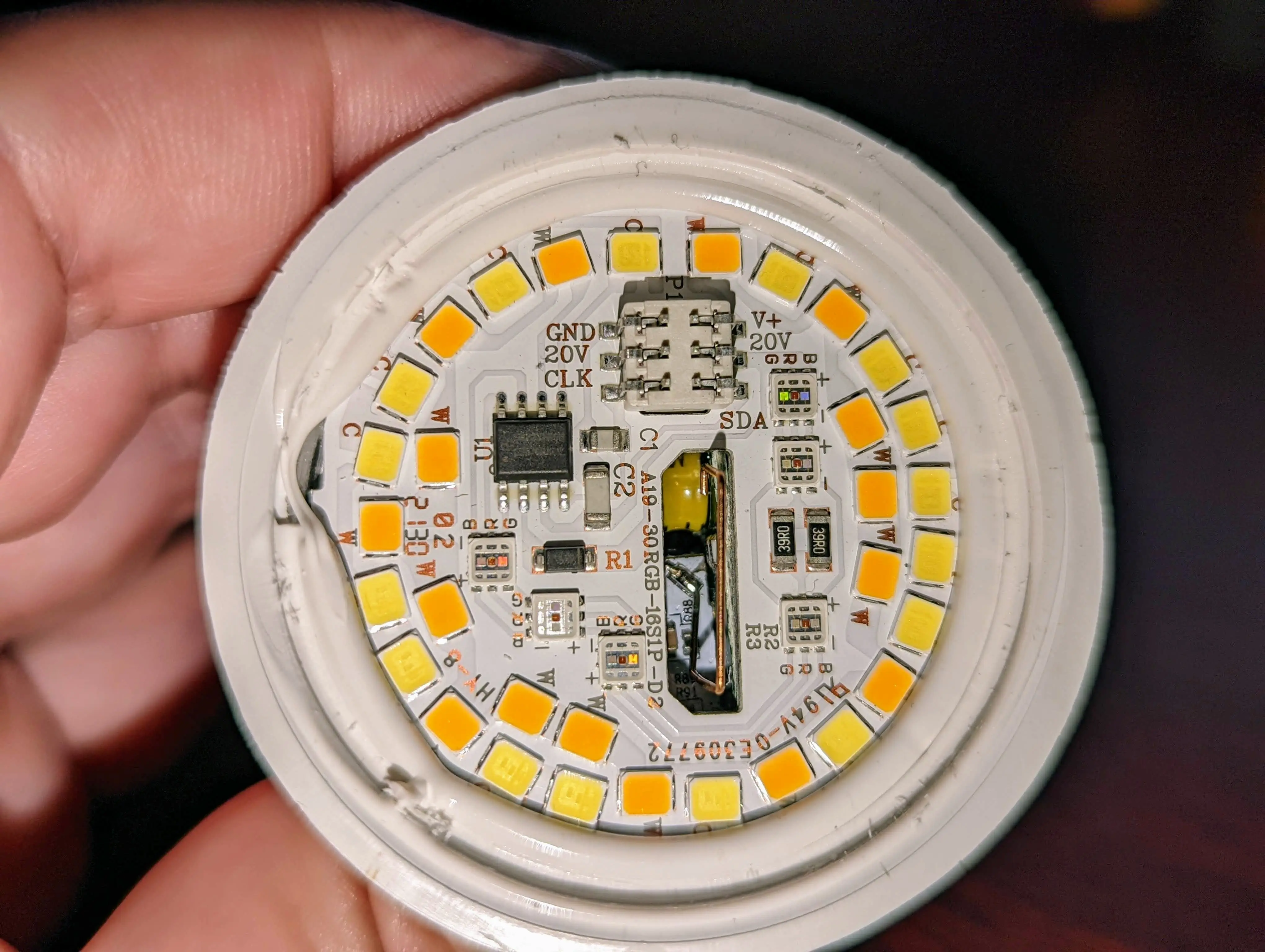
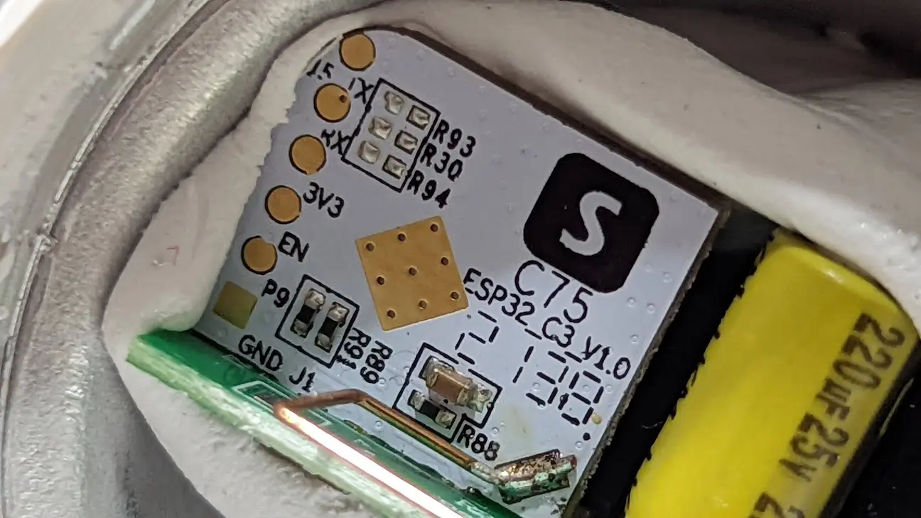
Pop the diffuser off with a spudger. Remove the silicone around the edge of the LED board. Use a spudger again to remove this board as it just using tension connector pins. It might stick a little especially if the bulb is cold. You will see the back of the ESP32-C3 for manual serial flashing if needed.
The P9 pad is like GPIO 0 in the ESP32-C3 world, it needs to be grounded at power up to enter into bootloader mode. ESP32 flashing procedures


