Smart Ambiance Light SAL001S
Purchase via Amazon
Thanks to Caleb for this awesome tutorial!
Sold under many different product brands:
- Halussoer
- Lzaonzoe
- Lumary
- Cakuja
- Dekala
- JVAXS
- winees
3/31/2022 - This device has a secondary MCU and a Beken chip. We will swap in ESP12F Chip and clip off the secondary MCU because it won't be needed.
Pinouts
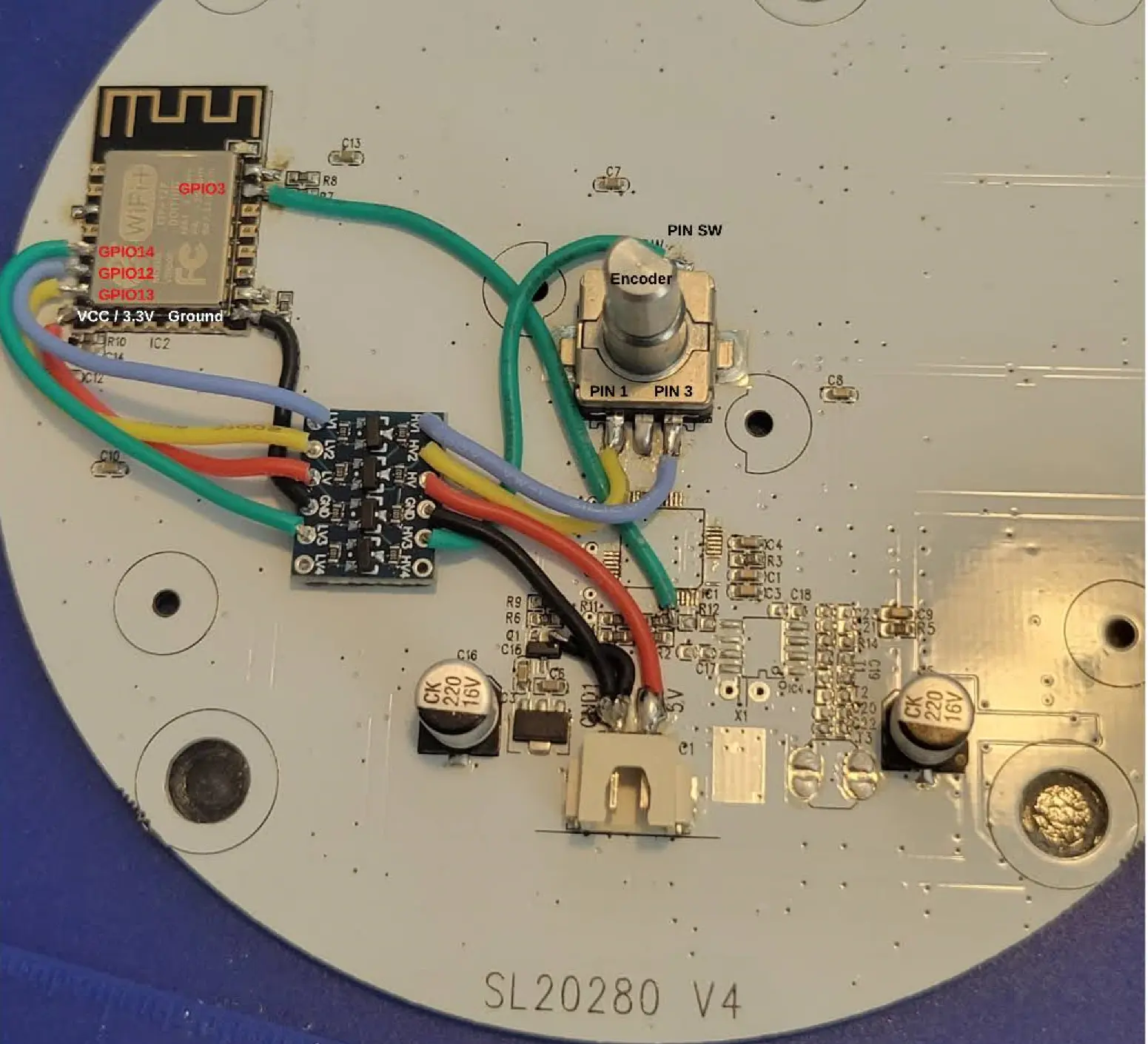
GPIO Layout
| GPIO | Component | Description |
|---|---|---|
| GPIO00 | None | |
| GPIO01 | None | |
| GPIO02 | ESP12F LED | On board LED of the ESP12F chip |
| GPIO03 | None | Data pin for LEDs |
| GPIO04 | None | |
| GPIO05 | None | |
| GPIO09 | None | |
| GPIO10 | None | |
| GPIO12 | Encoder Pin 1 | Encoders far left pin |
| GPIO13 | Encoder Pin 3 | Encoders far right pin |
| GPIO14 | Encoder SW | Encoders push button switch pin |
| GPIO15 | None | |
| GPIO16 | None |
Additional Hardware
You'll need to buy yourself an
If you want to use the rotary encoder on the back you'll need a voltage logic level shifter due to the board having 5V supplied and the ESP chip only tolerating 3.3v on it's pins
Pre-Flash ESP12F
Chip Flashing
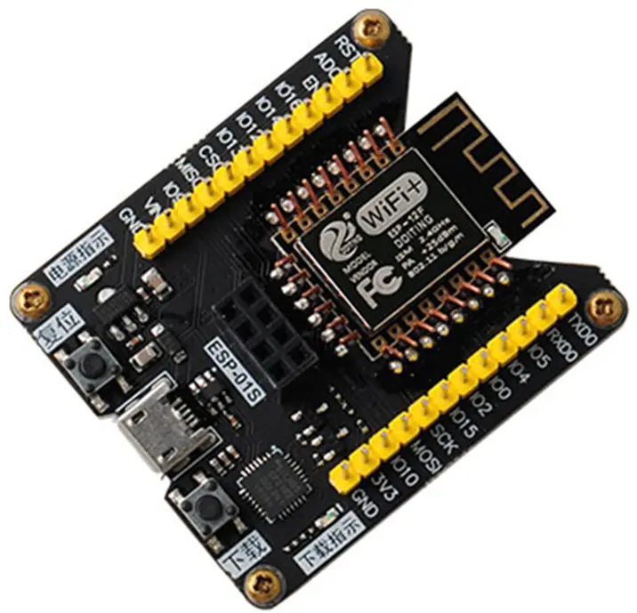
Let's start by just flashing a normal release of WLED by visiting the web installer of WLED.
If you want to use the encoder on the back you'll have to compile WLED with the encoder usermod and flash that binary.
To setup VSCode/Platformio to compile visit here
Details can be found here
Here is a sample of the platformio_override.ini file used
[platformio]
default_envs = WLED_SAL001S

[env:WLED_SAL001S]
board = nodemcuv2
platform = ${common.platform_wled_default}
platform_packages = ${common.platform_packages}
board_build.ldscript = ${common.ldscript_4m1m}
build_unflags = ${common.build_unflags}
build_flags = ${common.build_flags_esp8266} -D WLED_RELEASE_NAME=SAL001S -D USERMOD_ROTARY_ENCODER_BRIGHTNESS_COLOR
lib_deps = ${esp8266.lib_deps}
After you build/compile the code it'll show up in the directory build_output/release/WLED_VERSION_SAL001S.bin
Feel free do the manual firmware OTA in the wled web ui /settings/sec?
Open it
Drop it like it's hot
Drop it on the floor. Don't throw it but drop it and the two halves will pop open.
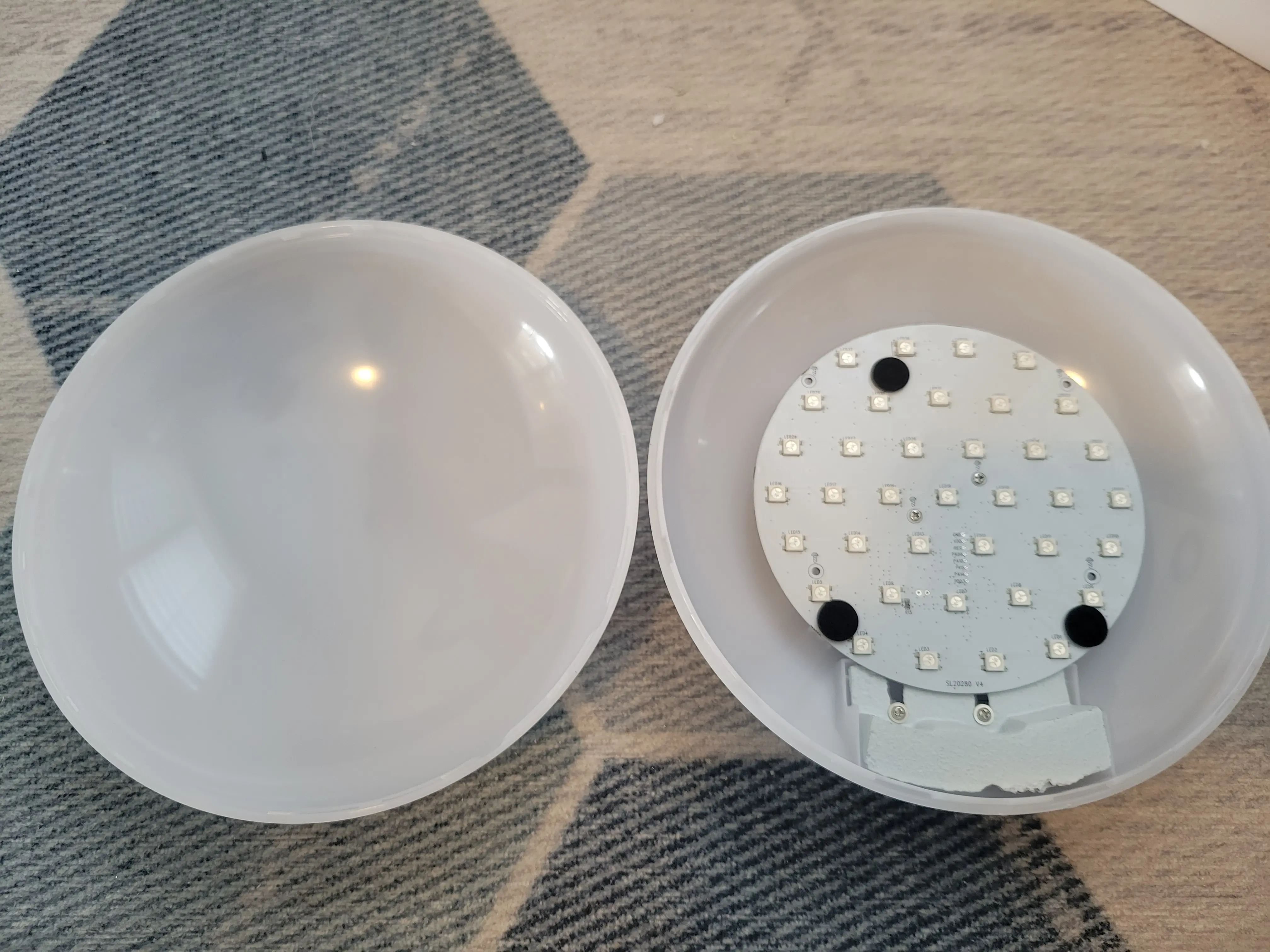
Remove the two screws in the middle of the PCB and pull the board out.
Detach the power wires and the board should come free and you'll see the chips on the back and the LEDs on the front
Desolder un-needed components
Add Leaded Solder
Get some leaded solder and melt some on the existing pins of the WBR3 chip
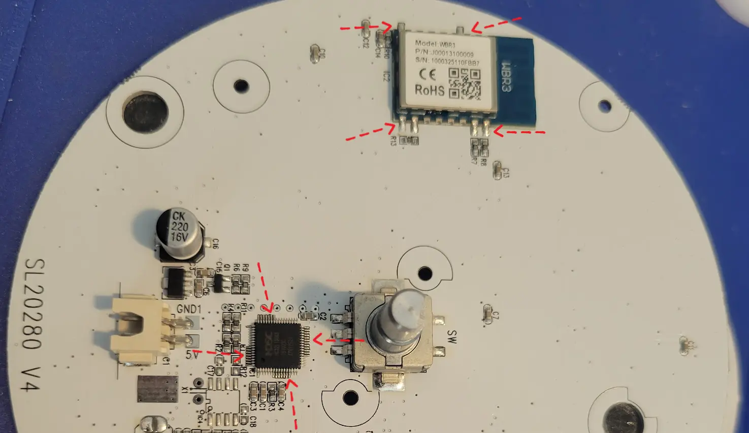
Heat em up! Pull em off! RAWHIDE!
Now use your hot air tool, soldering iron, or heat gun to remove the chips
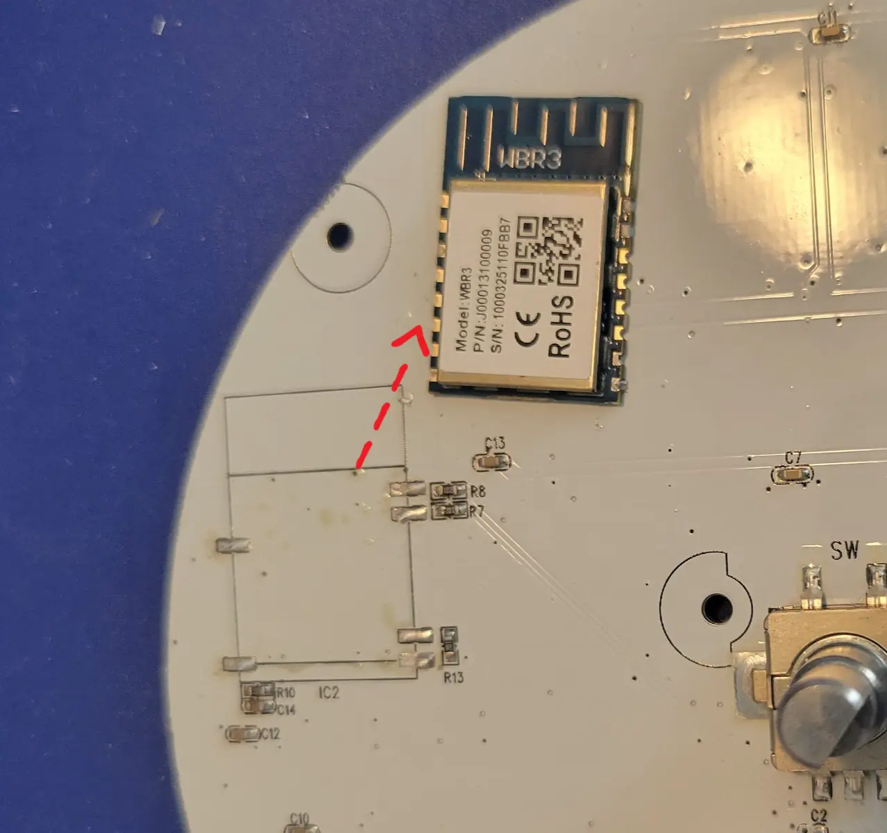
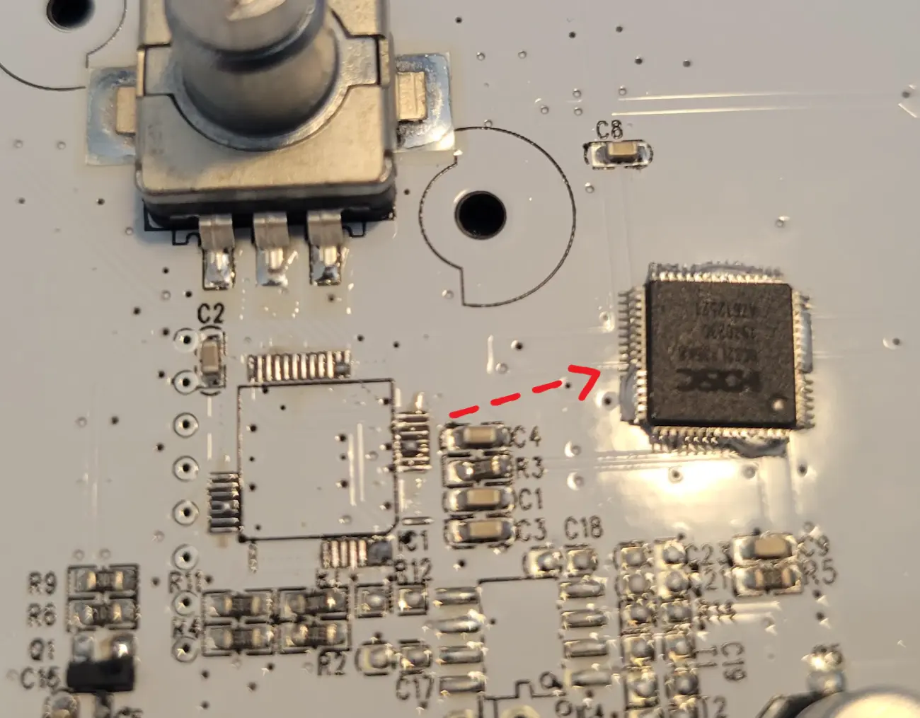
Solder new stuff
Now we want to solder the needed jumpers and chip back on
ESP12F
Use some solder wick and clean up the pads where you pulled the WBR3 chip from, this will allow the ESP12F chip to sit flat on the PCB
Place the ESP12F on the board and solder it into place
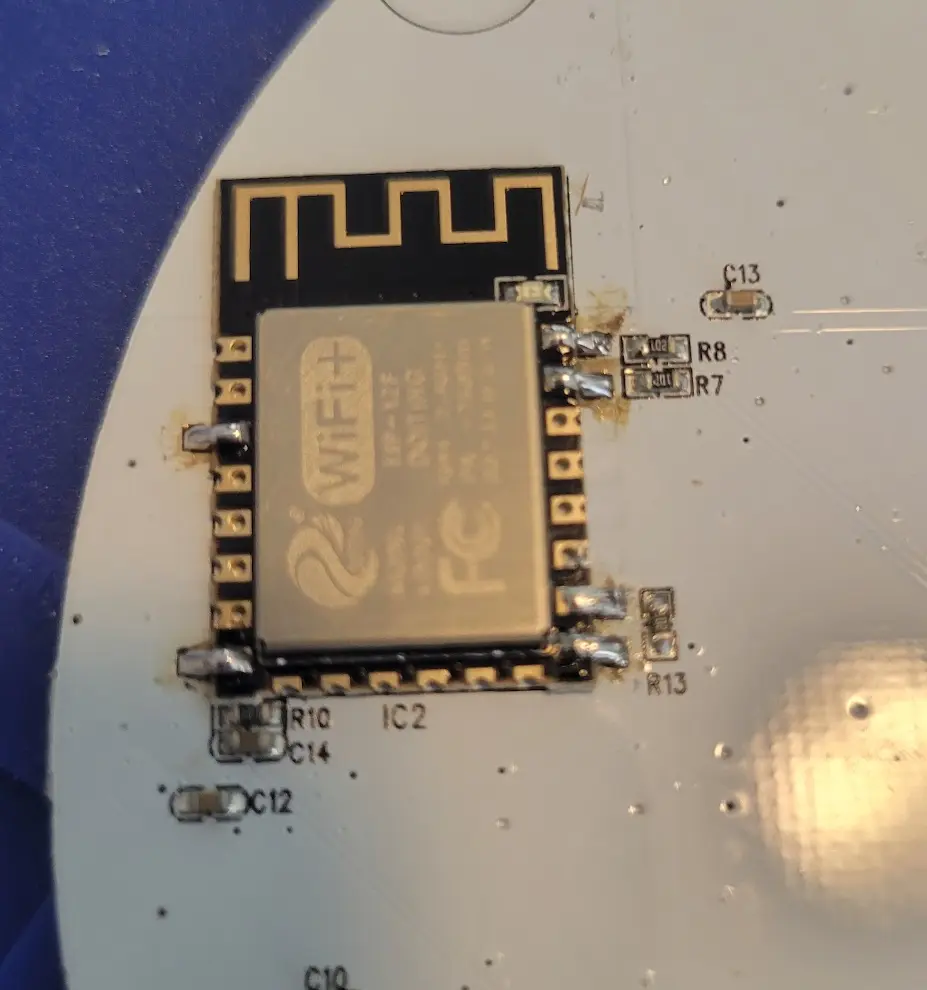
Data Pin Jumper
The secondary MCU used to drive the data pin of the LEDS. We removed that chip and need to jump a wire from the where it connected to our ESP12F chip
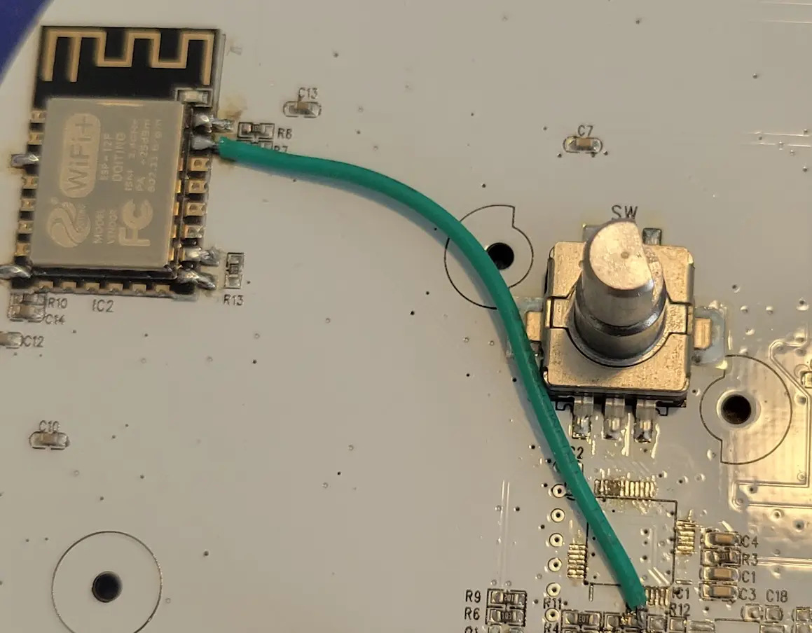
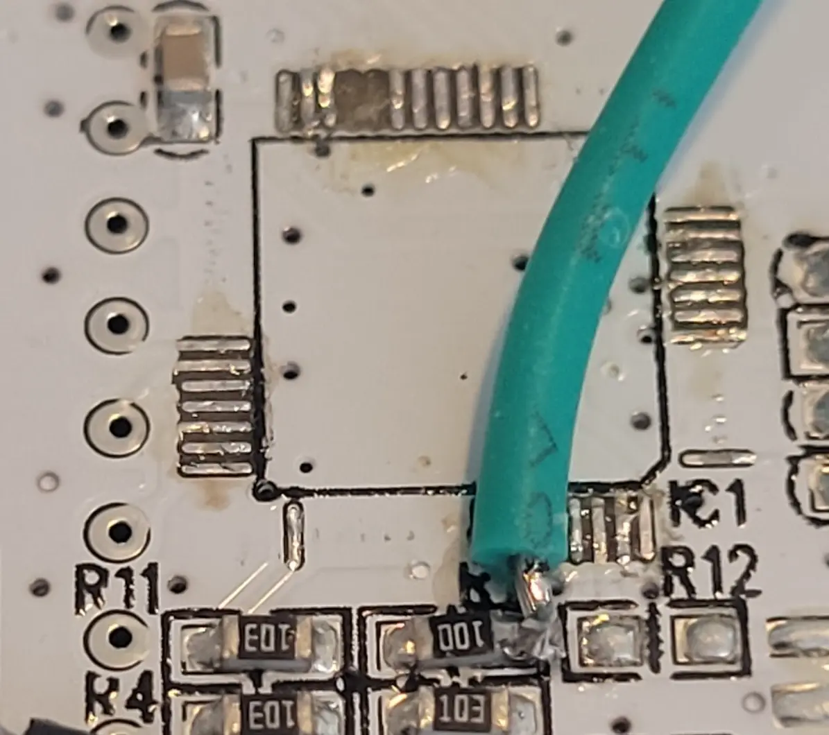
Ground Pin Jumper
With the secondary MCU removed we need to re-attach to the ground properly. Take a small piece of wire and solder like shown here
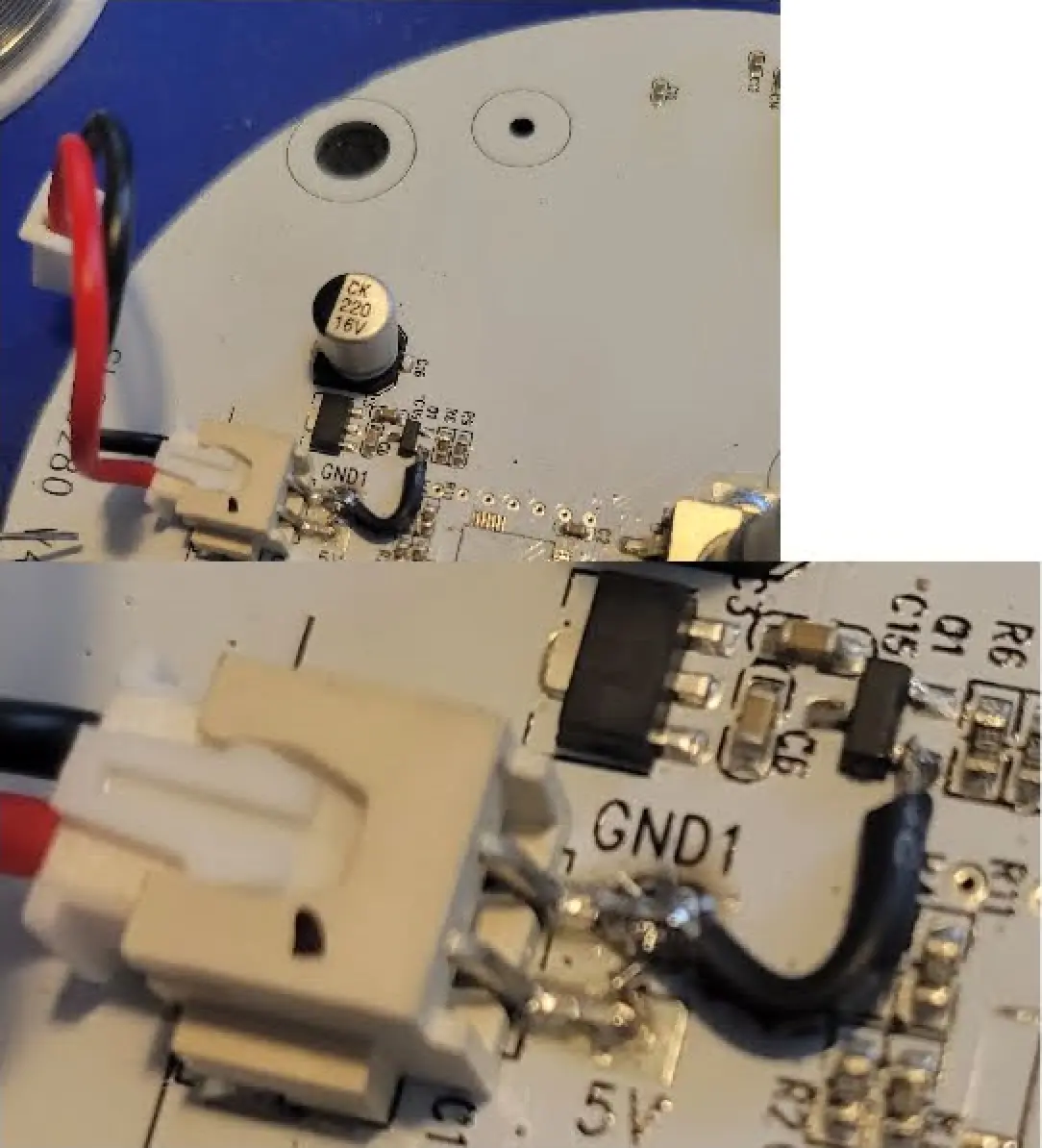
If you're not using the encoder you can stop here and re-assemble the unit and move on to the WLED settings section.
Logic Level Shifter Board
Feel free to use any color wires you'd like.
| ESP12F | LLC-LV | LLC-HV | Board Component |
|---|---|---|---|
| VCC | LV | HV | 5V |
| Ground | GND | GND | GND1 |
| GPIO12 | LV1 | HV1 | Encoder Pin 1 |
| GPIO13 | LV2 | HV2 | Encoder Pin 3 |
| GPIO14 | LV3 | HV3 | Encoder SW |
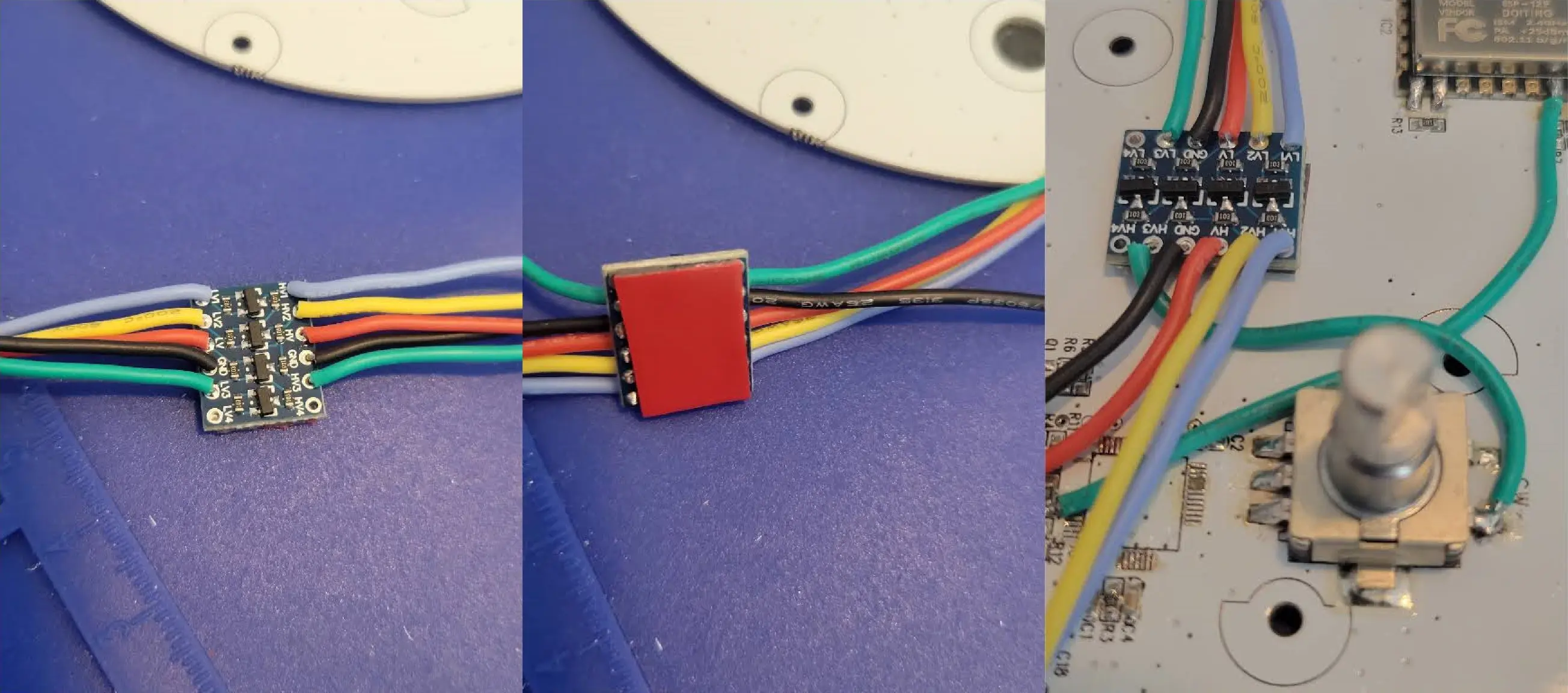
Adhere the board with some double sided adhesive
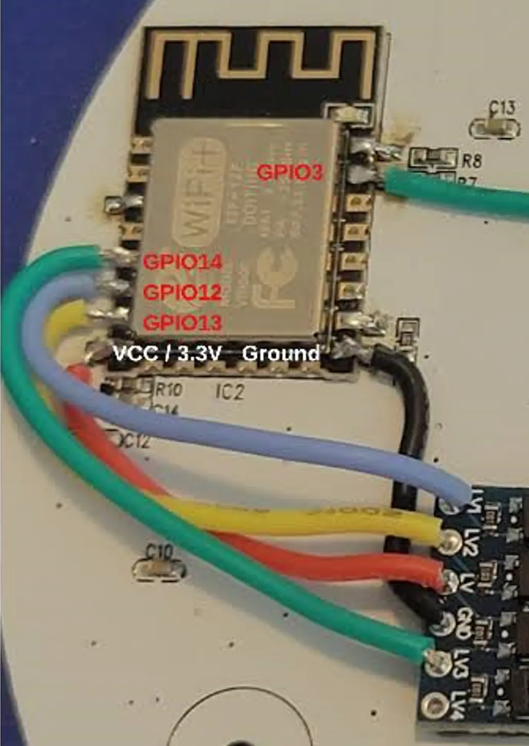
ESP12F to LLC Board
Wire up the 3.3V power and ground
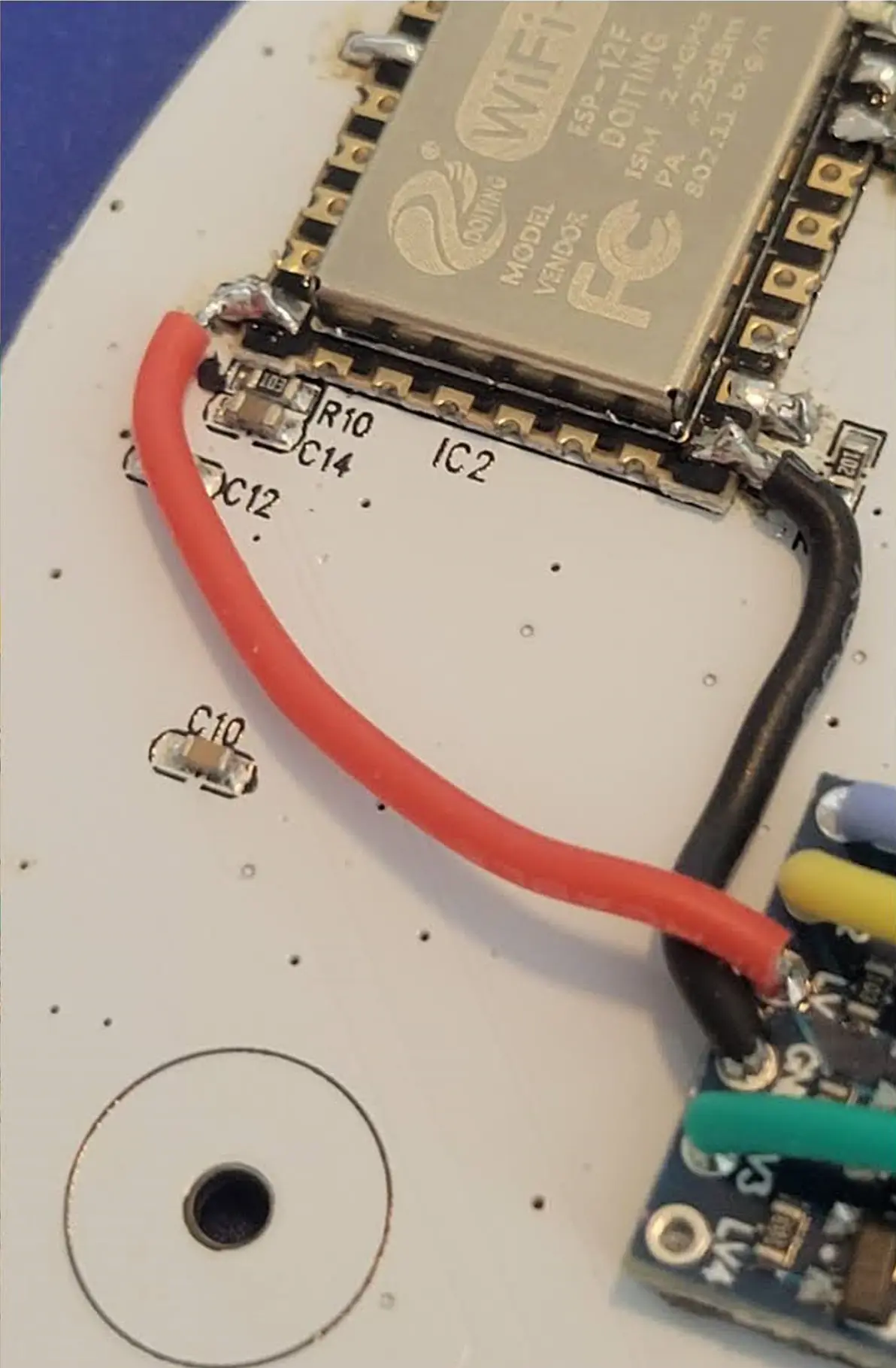
Here is a pic of the jumper wirings going to the ESP12F chip
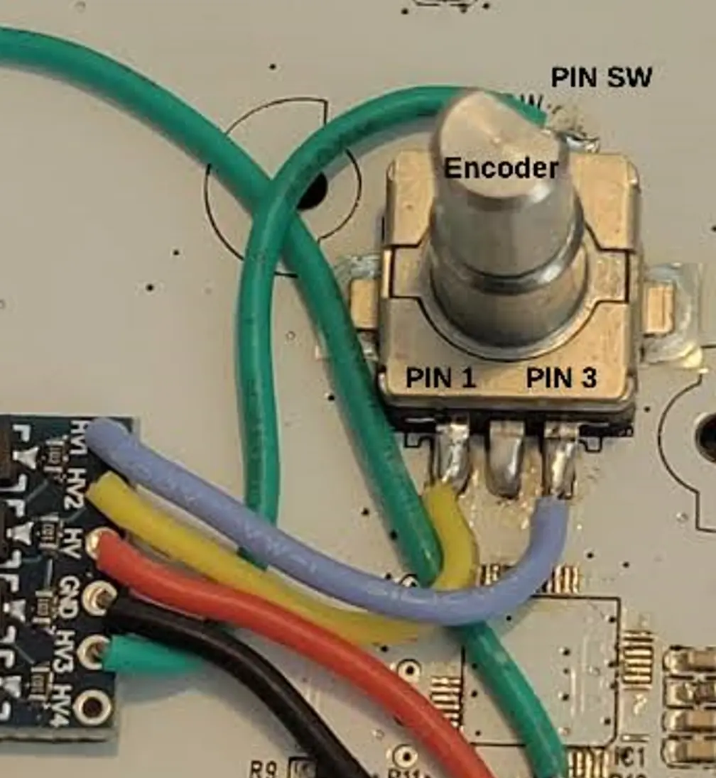
Components to LLC Board
Wire up the 5V power and ground
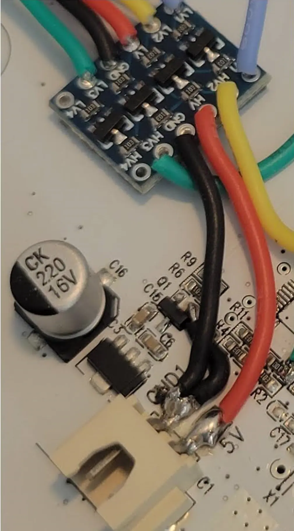
Here is a pic of the jumper wirings going to the ESP12F chip
WLED Settings
General
| Location | Setting | Value | Description |
|---|---|---|---|
| /settings/leds? | Maximum Current | 2500 mA | The power supply provided can do up to 2.5 amps |
| /settings/leds? | LED1 Type | WS281x | Main lamp LED type |
| /settings/leds? | LED1 Color Order | RGB | Main lamp LED color order |
| /settings/leds? | LED1 Length | 37 | Main lamp LED count on the face of the lamp |
| /settings/leds? | LED1 GPIO | 3 | Main lamp LED GPIO pin |
| /settings/leds? | LED2 Length | 1 | ESP12F single LED |
| /settings/leds? | LED2 GPIO | 2 | ESP12F single LED GPIO pin |
| /settings/leds? | LED2 Inverted | checked | ESP12F single LED turned off by default |
| /settings/leds? | Relay GPIO | -1 | Need to change this from the defaulf of 12 |
Encoder Usermod
This section is only needed if you've wired up the encoder as shown above
| Location | Name | Setting |
|---|---|---|
| /settings/um? | pin1 | 12 |
| /settings/um? | pin2 | 13 |
| /settings/um? | pin3 | 14 |