
A little different style video talking about the future of the ESP8266 in the local control Smart Home IoT World.  Video - https://youtu.be/hskofG2eiGs

Transplanting an ESP Module - https://www.digiblur.com/2020/12/treatlife-dual-indoor-dimmable-smart.html
RTL Arduino SDK - https://www.amebaiot.com/en/ameba-arduino-getting-started-rtl8710/

⚡Other Resources

How to Flash with the Jig - https://youtu.be/imKZbhJ8lvU

⚡Products We Use/Recommend
Amazon US - https://amzn.to/2YZNDeO
Amazon UK - https://amzn.to/2TnG2R4
Amazon CA - https://amzn.to/2JWsNq5

⚡Connect!⚡
Discord Chat - https://discord.gg/bNtTF2v
Patreon - https://www.patreon.com/digiblurDIY
Instagram - https://www.instagram.com/digiblurdiy

DISCLAIMER: I am a participant in the Amazon Services LLC Associates Program, an affiliate advertising program designed to provide a means for this channel to earn commissions by linking to Amazon.com and affiliated sites.  Most or all product links are affiliate links and digiblurDIY could receive compensation if used.

Treatlife Dual Indoor Dimmable Smart Plug (DP-20) ESP Transplant

Submitted by M.J. Wydra
https://github.com/Tediore

Treatlife released an indoor dual outlet dimmable smart plug in Q4 2020. It ships with a WB3S module which is not compatible with Tasmota but is pin-compatible with the ESP-12 (see the end of this document for a pinout comparison). This means the WB3S can be removed and replaced with an ESP-12 flashed with Tasmota.


The plug is held together with four screws and some internal clips. Remove the informational sticker on the back to access the four screws. Remove the screws and pry in the gap on the longer sides of the plug to open the plug up.


Unfortunately the plug is equipped with a secondary TuyaMCU (Nuvoton M031EC1AE, pictured to the left of the WB3S). This means the plug will use the Tasmota TuyaMCU module (Module 54) once the WB3S is replaced with an ESP.

Take care not to remove any of the pads when desoldering the WB3S. I accidentally removed the RX pad on the board when removing the chip (oops). This is a bad situation since this device has a TuyaMCU and relies on a connection between the ESP’s RX TX and the TuyaMCU’s TX RX. If this occurs you can either attempt to repair the connection or solder a wire from RX on the ESP to TX on the Nuvoton MCU. I moved the trace back into its place before soldering the ESP down and miraculously it works, but at some point I might need to open it up to fix it properly.


Picture of the final product with an ESP-12 in place of the WB3S. Note the red wire connecting GPIO15 to GND on the ESP. Without this connection the ESP will not boot to normal mode since there’s no pad on the PCB for GPIO15.

A Tasmota Template is not necessary, use the commands below on the Tasmota console.

The commands required to make the device work properly with Tasmota are similar to Treatlife’s DP-10 outdoor dimmer plug:

<table style="border-collapse: collapse; border: none;"><colgroup><col width="467"></colgroup><tbody><tr style="height: 0pt;"><td style="background-color: #434343; overflow-wrap: break-word; overflow: hidden; padding: 5pt; vertical-align: top;"><p dir="ltr" style="line-height: 1.2; margin-bottom: 0pt; margin-top: 0pt;"><span face="Consolas, sans-serif" style="background-color: transparent; color: white; font-size: 12pt; font-variant-east-asian: normal; font-variant-numeric: normal; vertical-align: baseline; white-space: pre-wrap;">Module 54</span></p></td></tr><tr style="height: 0pt;"><td style="background-color: #434343; overflow-wrap: break-word; overflow: hidden; padding: 5pt; vertical-align: top;"><p dir="ltr" style="line-height: 1.38; margin-bottom: 0pt; margin-top: 0pt;"><span face="Consolas, sans-serif" style="background-color: transparent; color: white; font-size: 12pt; font-variant-east-asian: normal; font-variant-numeric: normal; vertical-align: baseline; white-space: pre-wrap;">Backlog TuyaMCU 21,2; SetOption20 1; SetOption54 1</span></p></td></tr><tr style="height: 0pt;"><td style="background-color: #434343; overflow-wrap: break-word; overflow: hidden; padding: 5pt; vertical-align: top;"><p dir="ltr" style="line-height: 1.38; margin-bottom: 0pt; margin-top: 0pt;"><span face="Consolas, sans-serif" style="background-color: transparent; color: white; font-size: 12pt; font-variant-east-asian: normal; font-variant-numeric: normal; vertical-align: baseline; white-space: pre-wrap;">Backlog TuyaSend2 3,100; DimmerRange 10,1000</span></p></td></tr></tbody></table>

Depending on the light bulbs you use with this device, you might need to modify the DimmerRange command with a different low value. Both outlets are controlled at the same time (no independent control), and the lights gradually fade when turned on or off. Unfortunately it does not fade between brightness levels.

Pinout comparison (WB3S on the left, ESP-12 on the right):

Submitted by M.J. Wydra
https://github.com/Tediore

I started with 7 cameras in the comparison but the wheels quickly fell off of 3, leaving 4 great cameras and even a couple of them bring Starlight lenses and 4K to the table.  

Amcrest 5MP - https://amzn.to/2TjVUVq
Reolink RLC-520 5MP - https://amzn.to/35oD5Gv
Amcrest 4K 8MP Bullet - https://amzn.to/3mhtPL9
Amcrest 4K 8MP Turret (not shown in video) - https://amzn.to/3mkoAKA
Annke C800 4K 8MP - https://amzn.to/3ohq5Lb

How to put Ethernet Cable Ends on for POE Cameras - https://youtu.be/p1vwjhvHKLI
GoPro Hero 9 - https://amzn.to/2TkuxuE

-=-=-=-Products We Use/Recommend-=-=-=-

Amazon US - https://amzn.to/2YZNDeO

Amazon UK - https://amzn.to/2TnG2R4

Amazon CA - https://amzn.to/2HchPZe

DISCLAIMER: I am a participant in the Amazon Services LLC Associates Program, an affiliate advertising program designed to provide a means for this channel to earn commissions by linking to Amazon.com and affiliated sites.  Most or all product links are affiliate links and digiblurDIY could receive compensation if used.

-=-=-=-Connect!-=-=-=-

Discord Chat - https://discord.gg/bNtTF2v

Patreon - https://www.patreon.com/digiblurDIY

Links to products provided through the Amazon Affiliate program.

Are you just as tired as I was digging for stuff you go to all the time in Home Assistant?  I know I was!  The developers always seemed to move stuff on me too.  I wanted my Server Control, Integrations, and MQTT devices right at my finger tips instead of buried in menus and large integration panels lists.  I seem to get asked this question on every live stream which is a good thing!  So here's how to do it, it's simple.  

Open your configuration.yaml file in whatever method you like to edit files, VSC, Notepad++, vi, etc. Make sure you do not have a "panel_custom:" section already.  If not, just copy and paste this one in.  

panel_custom:

  - name: ha_server_con

    sidebar_title: ServerControl

    sidebar_icon: mdi:cog-transfer

    js_url: /api/hassio/app/entrypoint.js

    url_path: 'config/server_control'

    embed_iframe: true

    require_admin: true

    config:

      ingress: core_configurator  

  - name: ha_mqtt_dev

    sidebar_title: MQTT Devices

    sidebar_icon: mdi:chip

    js_url: /api/hassio/app/entrypoint.js

    url_path: 'config/devices/dashboard?historyBack=1&config_entry=abcdefgh123456xxxxxxx'

    embed_iframe: true

    require_admin: true

    config:

      ingress: core_configurator        

  - name: ha_integ

    sidebar_title: Integrations

    sidebar_icon: mdi:checkerboard

    js_url: /api/hassio/app/entrypoint.js

    url_path: 'config/integrations'

    embed_iframe: true

    require_admin: true

    config:

      ingress: core_configurator  

"But I run Core and not Hassio/OS!"  Don't worry.  I run Core as well and this still works.  One thing everyone will need to change is the config_entry code as seems to be unique per install.  Open your Integrations and right click on the MQTT Devices and copy the URL.  The URL will have your unique config_entry code.  Replace it over the one above, only paste in the config_entry code, not the entire URL!  Save your configuration yaml file.

For one last time, dig around for Server Control, do the Check Configuration.  If everything passes, hit restart.  Once Home Assistant restarts you'll have the new panels.  Don't forget, you can long left mouse click on the "Home Assistant" title to change the order and hide each panel as needed.  

What other panels have you added?  Please share them! 

🔥📞Connect!☎️🔥

Discord Chat - https://discord.gg/bNtTF2v

Patreon - https://www.patreon.com/digiblurDIY
Instagram - https://www.instagram.com/digiblurDIY


🔥⚡Products We Use/Recommend⚡🔥
Amazon US - https://amzn.to/2YZNDeO
Amazon UK - https://amzn.to/2TnG2R4
Amazon CA - https://amzn.to/2JWsNq5


DISCLAIMER: I am a participant in the Amazon Services LLC Associates Program, an affiliate advertising program designed to provide a means for this channel to earn commissions by linking to Amazon.com and affiliated sites. Most or all product links are affiliate links and digiblurDIY could receive compensation if used.

I had the pleasure (or not) of testing out another PTZ camera.  I'm always down on checking out a new one after the last three I checked out, such as the Amcrest, Reolink and I'll not mention the last one that didn't fair to well in a video.  PTZ cameras are addicting and useful to complement your fixed position cameras, once you go PTZ you can't go back!

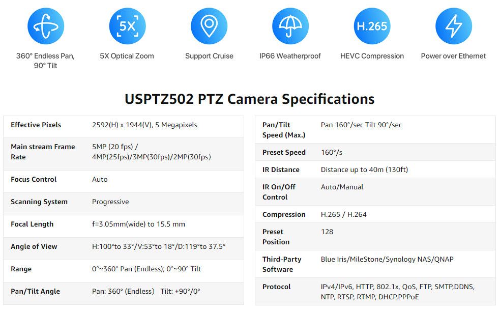
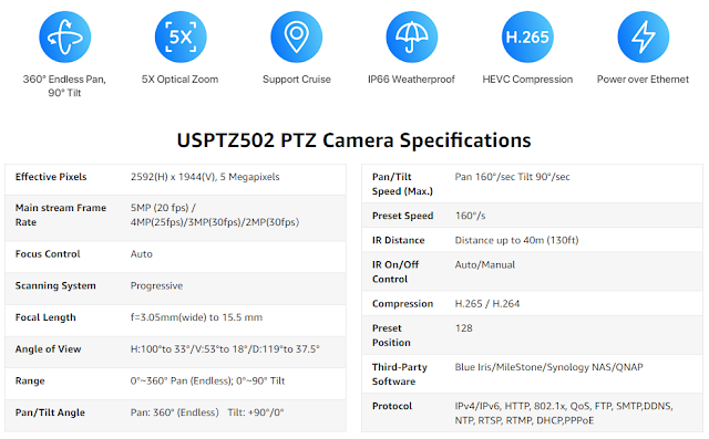
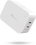
The H.View PTZ 502 is a 5MP camera with 5x optical zoom and is POE capable, even at non POE+ specs it works!  Other PTZs we've had to use POE+ for additional power.  Speaking of that at first glance I noticed something....

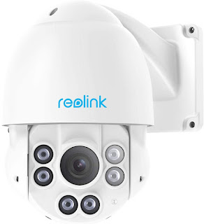
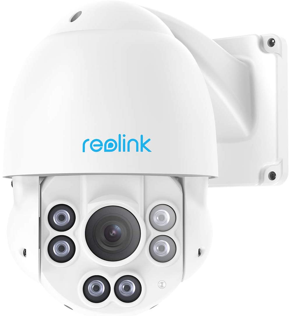
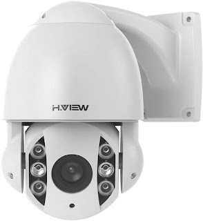
I had seen this camera before!  Well at least the shell of the camera.  The lens part was a little different but it was almost the same housing.  The Reolink is only 4x though instead of the H.View being 5x.  The one drawback I had with the Reolink was the speed of moving and focus took too long, especially after we got spoiled with the Amcrest PTZ camera. 

After opening the box I decided to check out the non POE+ claim to see if it would power up.  Sure enough it did!  But what did they give up to have lower power requirements?  Let's find out!  I looked on my router's camera VLAN for a new device IP address.  Hmm...There wasn't one?  Maybe the POE+ is required, so I tested it on a POE+ switch.  Still no IP!  That's strange, usually if I plug in other cameras they just pull an IP address via DHCP and you can browse to the web GUI.  So I looked on the label and sure enough it had the issue, out of the box it is setup for 192.168.1.20 as a static IP.  WOW!  Failure #1.  Don't assume everyone has a network range like that along with that IP being open. Luckily I had an old router I was able to fire up and attach this camera to it, browse to the static IP, change it to DHCP then plug it back into my network.  Alrighty, off and running now!

Browse to the IP and no video screen feed comes up.  After a bit of digging it seems to require Adobe Flash that of course is being discontinued this month (Dec 2020).  I emailed the manufacturer after not seeing a firmware update on their website.  They immediately sent a new firmware BIN file to upload to the camera.  I do find it very strange for a camera manufacturer to host their firmware updates on a Google Drive instead of their website.  Seem sketchy to you?  

So after all these hoops to jump through we were finally off and running!  

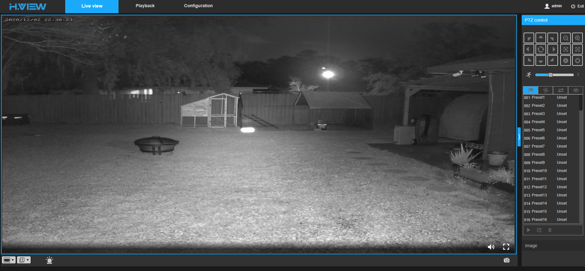
Of course like a kid in a candy store I wanted to check out the PTZ controls.  I did find the web GUI to have a bit of delay which was making it hard to control, much like doing a remote screen share via satellite internet.  It was a little better if I opened up an RTSP stream to see it but I still found it to be somewhat slow compared to other cameras.  A quick check of the specs and sure enough, 160 degrees/sec compared to the what I thought was slower, the Reolink has a spec of 180 degress/sec.  That must be the difference in not requiring POE+ power with this camera.

I was able to pull it right into Blue Iris without any issue, control all the PTZ directions, pull in both main and sub streams as well.  Check mark there for the camera!

As you can tell I've had issue after issue with this camera, but wait there's more!  After a power outage the camera ends up pointing downward and backwards. What? Maybe there's a return to position setting that isn't set?  I couldn't find one in the web GUI to make it return to the last position.  Another issue I found was I would check back on the camera at various times of the day and find it not focused.   It would be all blurry and I'd have to focus it manually.  I'm not sure what was causing this issue.  If I zoomed it all the way in it seemed to fix the focus for a while though.  

So would I buy or recommend this camera?  Nope, currently as of 12/2/2020 it's priced at $280 USD with 10% off ($252..prices subject to change).  It's more expensive, slower, no SD card option and various other issues.  I definitely pick up the Reolink RLC-423 for less or for a $30-$40 more I'd just jump for a Amcrest PTZ and get 12x zoom and more speed.  

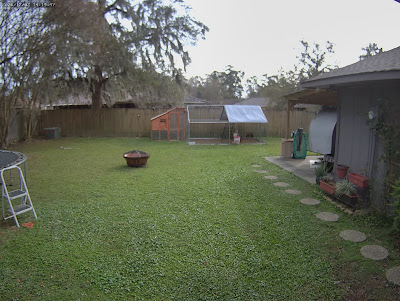
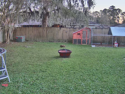
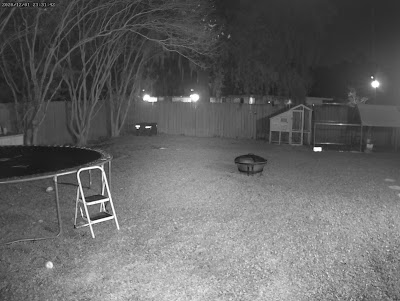
Once the issues with the firmware, focusing, speed, etc get resolved possibly we could do some video review footage of the camera, until now here are a few clips.  It isn't hammer time just yet! :)

Snapshot using the snap feature of the GUI

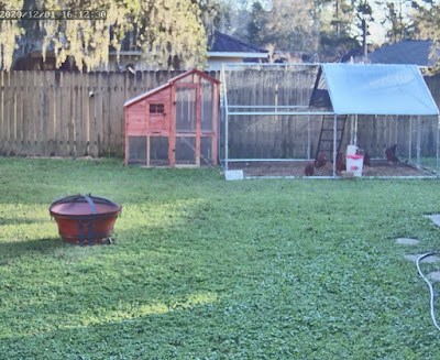
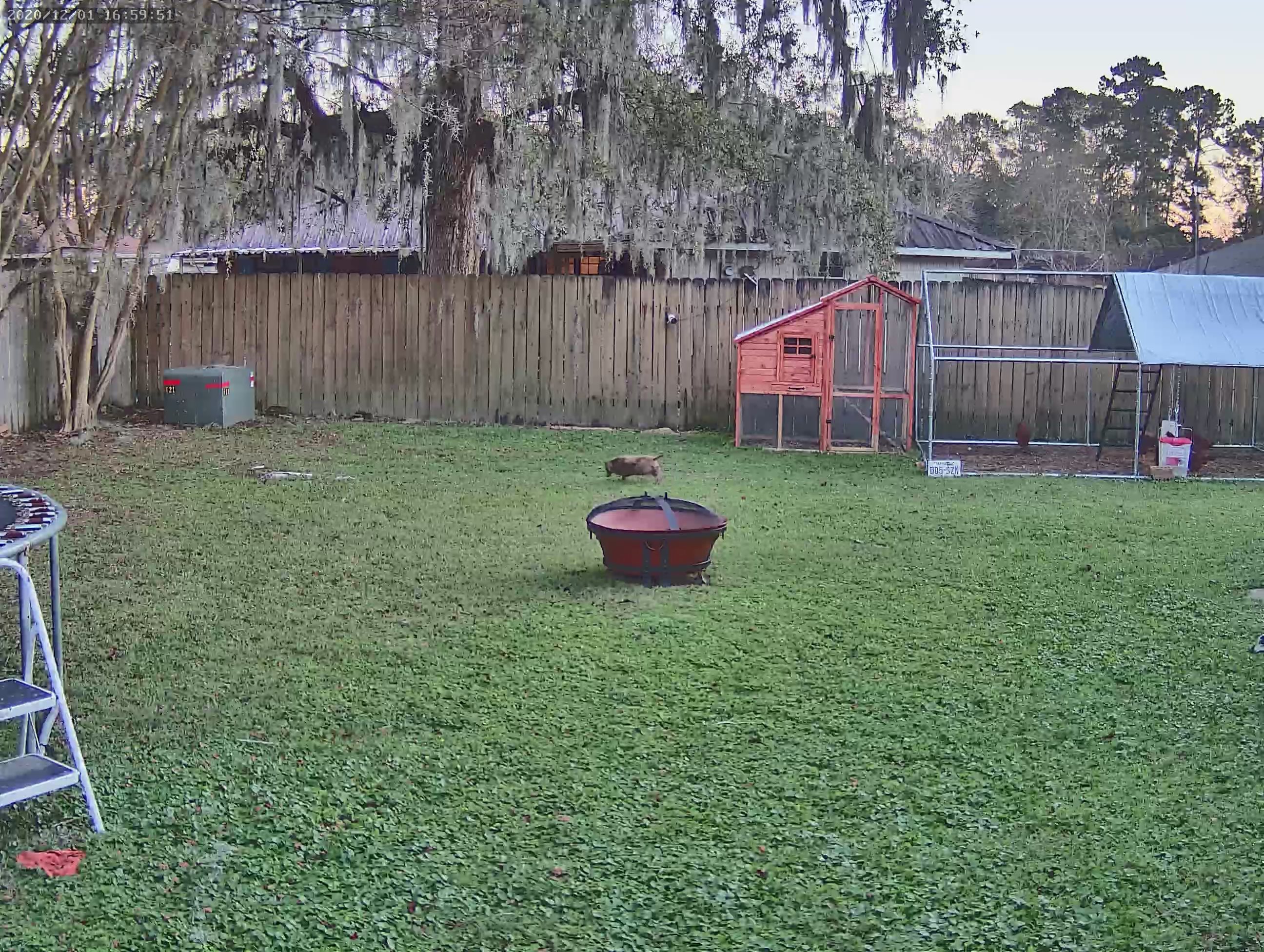
Snapshots pulled via the RTSP main stream feed (some might be out of focus due to the auto focus issue)

-=-=-=-Connect!-=-=-=-

Discord Chat - https://discord.gg/bNtTF2v

Patreon - https://www.patreon.com/digiblurDIY

DISCLAIMER: I am a participant in the Amazon Services LLC Associates Program, an affiliate advertising program designed to provide a means for me to earn commissions by linking to Amazon.com and affiliated sites.  Most or all product links are affiliate links and digiblurDIY will receive compensation if used.

At first I didn't want to believe it but there's no going back to using the old school RJ-45 connectors for Cat5e or Cat6 cables.  Pass through has definitely spoiled me after doing a few of them especially up on the ladder at 8pm on the eave of the house.  

Cable Crimper - https://amzn.to/2TGbytY

Cable Stripper - https://amzn.to/2ws16ys or https://amzn.to/3i3iVpx

Cable Ends - https://amzn.to/2TzyH1k

Cable Tester - https://amzn.to/3n4J3nY

Cat5e Cable - https://amzn.to/2ZakBp0 or https://amzn.to/2WmLPtn

Fiberglass Wire Fishing Sticks - https://amzn.to/2UhCLS0

MANDATORY DISCLAIMER: I am a participant in the Amazon Services LLC Associates Program, an affiliate advertising program designed to provide a means for me to earn commissions by linking to Amazon.com and affiliated sites.  Most or all product links are affiliate links and digiblurDIY will receive compensation if used.

-=-=-=-Connect!-=-=-=-

Discord Chat - https://discord.gg/bNtTF2v

Patreon - https://www.patreon.com/digiblurDIY

(Don't forget the 30% coupon code towards the end of this post!)

UPDATE 2020/11/01 - Notice posted on their website:

Notice:

The product purchased ealier than 20th Oct are 2m bin which is not compaitble wih official Tasmota OTA server. After 20th Oct 2020, the product changed to standard 1m bin and fully compatible with official Tasmota OTA server

You heard correctly.  No flashing, no jumper wires, no soldering, no Tuya Convert, etc., take the smart bulb, switch, plug, etc., out of the box, plug it in and it is ready to go!  The device will be in access point mode ready to add to your Wi-Fi network.  ESPHome users can easily apply their own configuration to use them as well!  

But why do we need this?  Can't we just flash our own devices?  Absolutely! If you have the skills and know how to flash the all of your devices then this might not be for you.  

Do you just want something ready to go?  Keep reading, more and more smart home devices such as Smart Bulbs and Smart Plugs are almost impossible to flash via soldering/jig methods due to the pins not being accessible.  Then let's not forget, many smart devices have moved to RTL based chipsets that can't be flashed with Tasmota/ESPHome at all.

A company name ATHOM Technology is bringing several devices to the table to help break down the barriers of having a true smart home that isn't dependent on the cloud and possibly some company selling your data.  It reminds me of the exciting times where we could first start buying computers with Linux installed and didn't have to pay for the Windows license!

I've looked at several of the products in this run and while one glaring issue I have upfront is the lack of open pin headers like you might see on a Shelly1 switch, you do have to keep in mind that things will only get better as hardware runs continue to improve and we voice our opinions with the company.  With that said, I was pleasantly surprised with the RGB+CCT (5 channel color) smart bulb brightness.

I do plan on doing a full review video of several of them but I have been delayed in my schedule with the current Hurricane Laura recovery efforts.  Instead of wasting more time for the ones that want to check this out right now, I'm doing this blog post to share a coupon code for 30% off on their store at https://athom.aliexpress.com/  just put in DIGIBLURDIY as the promo code.  UPDATE:  There are only 100 coupons available, once I get confirmation they are done, I'll edit this post.   

Stay tuned to the digiblurDIY YouTube channel.... https://www.youtube.com/digiblurDIY

Upgrade procedures to the latest Tasmota (if you have a 2M or 4M flash-thanks @BigChief) . Go to the console and issue

reset 5

template 255

Copy this template to a temporary location then issue this command:

Module 19

Go ahead and upload the latest tasmota.gz file or tasmota-lite.gz file via the firmware upgrade button in the GUI. Do not use minimal. This is always the last resort file to use and isn't needed here. 

Once it is upgraded go back to the console and issue

Reset 5

Apply your template again from above.